The video at the right shows the bootloader operation. When the leftmost button (Mark High) is held down when the DSP TU is powered up, the DSP TU enters the bootload mode. All the button LEDs are lit to indicate the unit is in bootload mode. The button can be released once all the LEDs are lit. A terminal program, such as Tera Term is used to send new firmware to the DSP TU. If using Windows, the COM port can be identified using the Device Manager. On my computer, the DSP TU, which uses the FT231XS USB/UART bridge, shows up as COM5. Configure the serial port for 921,600 bits per second, 8 data bits, no parity, 1 stop bit, and XON/XOFF handshake. The terminal should be configured for local echo and CR for both transmit and receive newline.
When all the button LEDs are lit, the DSP TU is waiting for an Intel hex file to load into the program flash. On Tera Term, use the File -> Send File, then select the Intel hex file with the application code. Upon receiving the first valid line of hex (the checksum indicates the line is valid), the program flash is erased. The program flash is not erased until the first valid line of Intel hex is received to ensure the program flash is not erased accidentally. (If the system accidentally gets into bootload mode (all LEDs lit), turn the power off and back on again. The program flash has not yet been erased.) As each valid line of hex containing program data is received, the program flash is programmed 32 bit word by 32 bit word as the hex lines are received. A typical line contains 16 bytes, so four 32 bit words are programmed for each line. Since it takes time to erase flash and to program each word, the DSP TU bootloader sends XOFF to the host computer after each line with a valid checksum is received. It sends XON when it has finished processing the line, which typically has programmed several flash words. The host computer then sends the next line of the hex file. As each line of the hex file is programmed into program flash, the binary code shown on the button LEDs is incremented from the initial -1 (all on). This results in the LEDs flickering indicating that the hex file is being programmed into flash. If there is an overrun error (typically caused by XOn/XOFF handshake not being selected) or a bad checksum, an error message is sent to the terminal.
I had hoped to use a process similar to the above bootloaders where the linker script would be modified to place the application startup code and the application code in the program flash, and place a simple startup along with the bootloader in boot flash. However, the default linker script for this chip is very complicated and difficult to interpret. Several tries were made using this approach without success.
Microchip's Harmony provides a method of creating a bootloader. It is a separate application with its own startup code, linker script, etc. Then it is up to the user to modify the application's linker script to work with the bootloader. There are several example applications with linker scripts, but none for this chip. Here is the process I went through.
In MPLAB X, make the application (not the bootloader) the main project. Go to Tools - Embedded - MPLAB Harmony 3 Configurator. This should bring up the configuration you created for the application. It includes the peripherals and pin configuration for the application. Select File - Export to export the configuration created by Harmony.
Create a new project for the bootloader. Once again, go to Tools - Embedded - MPLAB Harmony 3 Configurator. Under "Available Components" select "UART Bootloader". This will add the Core Timer, NVM (non-volatile memory), and UART Bootloader to the Project Graph. Import the configuration saved from the application. This will add all the peripherals used in the application to the bootloader project. It will also set up the I/O pins and configuration registers. Delete the peripherals not used in the bootloader. Connect the remaining peripherals as shown in the image on the right on the Project Graph. In the DSP TU project, the UART is interrupt driven with input and output FIFO buffers. The Bootloader uses "blocking" polled UART code, so the UART is reconfigured in the bootloader project. This will cause Harmony to generate appropriate code for the bootloader. Tell Harmony to save the configuration and generate the code for the bootloader.
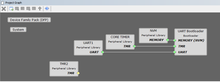
Bootloader project graph showing the required peripherals. Other peripherals imported form the application are removed.
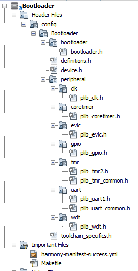
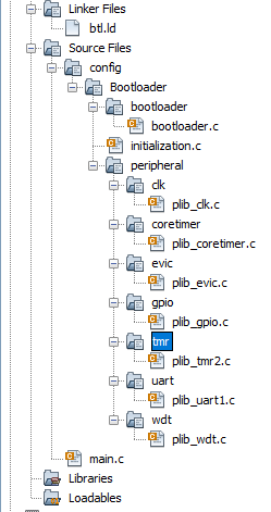
The images at the right show the header and source trees for the Bootloader project. Several unneeded header and source files generated by Harmony were removed or replaced with my own files. Note the linker file btl.ld. This was generated by Harmony and places the entire bootloader project in boot flash.
The bootloader project source code is located at https://github.com/HaroldHallikainen/Bootloader.
After running the C startup code, the bootloader runs main(). SYS_Initialize() was generated by Harmony. Some initialization code for unneeded modules (such as NV Memory) was deleted. The initialization sets the configuration bits and I/O pins to match the application code since we imported the appliction Harmony export into the bootloader Harmony. After GPIO Initialization, the leftmost pushbutton is checked. If it is not pressed, the run_Application is called. If the button IS down, the remainder of initialization is run. The initialization also initializes the UART as a polled peripheral.
After initialization, the bootloader_Task() (in bootloader.c) is called. The bootloader_Task was almost completely rewritten. In bootloader_Task() all the front LEDs are lit as an indication we are in the bootloader. The system loops until the button is released. The UART is then polled. Whenever a character is available, it is passed to InterpretIntelHex(). InterpretIntelHex looks for the start of record (colon), then buffers the received characters in an array. Once the record length has been received, it is used to determine the end of the record. After a complete record (line) has been received, the checksum is checked. If the checksum is good, an XOFF is sent to the UART so the host computer holds off sending more data while the record is interpreted. After the first valid record is received (good checksum), the application flash is erased. Waiting for the first good hex record helps prevent accidental erasure of the application flash. Erasure takes some time, so the previously mentioned XOFF holds off data so we do not overrun the UART.
As each record containing data is received, it is programmed into the appropriate 32 bit words in application flash. Once the record has been acted upon, XON is sent to the UART so the host can continue sending more data.
When the end of file record is received, the number of bad checksums is checked. If non-zero, an error message is sent to the UART for display on the host computer. Also, if there was a UART overrun (due to handshake not working), that error message is passed to the UART. If neither of these errors occurred, run_Application() is called. Run_Application() checks the first word of application memory to ensure it has been programmed (is not 0xffffffff). If it has been programmed, the application is run.
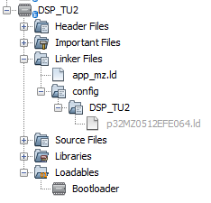
The image at the right shows the application file tree. Note especially that the default linker is grayed out (right click, exclude file(s) from current configuration). In addition, a new linker script app_mz.ld has been added. This compiles the application to run with the bootloader (entire application in program memory). If it is desired to run the application without the bootloader (startup in boot memory), the default linker can be included in the configuration and the app_mz.ld excluded from the configuration.
Note also that Bootloader is listed under Loadables. Right clicking on Loadables allows a project to be added to the application project. Here, the bootloader is added to the DSP TU2 application project. When DSP TU2 is compiled, DSP_TU2.X.production.unified.hex and DSP_TU2.X.production.hex are placed in the C:\Users\Harold_Win7\Documents\Microchip\Projects\DSP_TU2\firmware\DSP_TU2.X\dist\DSP_TU2\production directory (your location will vary based on where you put projects). The production.hex file is the application which can be bootloaded, while the unified.hex is the combined bootloader and application that can be used to program the entire chip with a production programmer.
Harmony does not offer the option of generating a linker script for a bootloaded application. Instead, it always generates a script for a standalone application. To find a linker script for a bootloaded application, we need to look at the Microchip provided sample projects. There is not a linker script for the PIC32MZ0512EFE064-I_PT. Instead, we can find a generic PIC32MZ-EF script. For example, on my system, I found C:\Users\Harold_Win7\Harmony3\bootloader_apps_uart\apps\uart_bootloader\test_app\firmware\src\config\pic32mz_ef_sk/app_mz.ld . I compared this with the standalone script generated by Harmony (p32MZ0512EFE064.ld) and modified the sample app_mz.ld to arrive at this
Ideally others can get a simple bootloader working based on this. There may be a need to protect code and not send out "plain text hex files." In that case, a decryption block could be inserted between receiving the character from the UART and sending it to InterpretIntelHex(). The hex file generated by MPLAB would be encrypted before sending it out. I have not tried this encrypted approach, but it seems like it could work.
I look forward to comments on Adventures in Bootloading.