Zero Five 30 Foot Flagpole Antenna
The
Zero Five 30 Foot Flagpole Antenna is a very sturdy vertical antenna that
doubles as a flagpole.
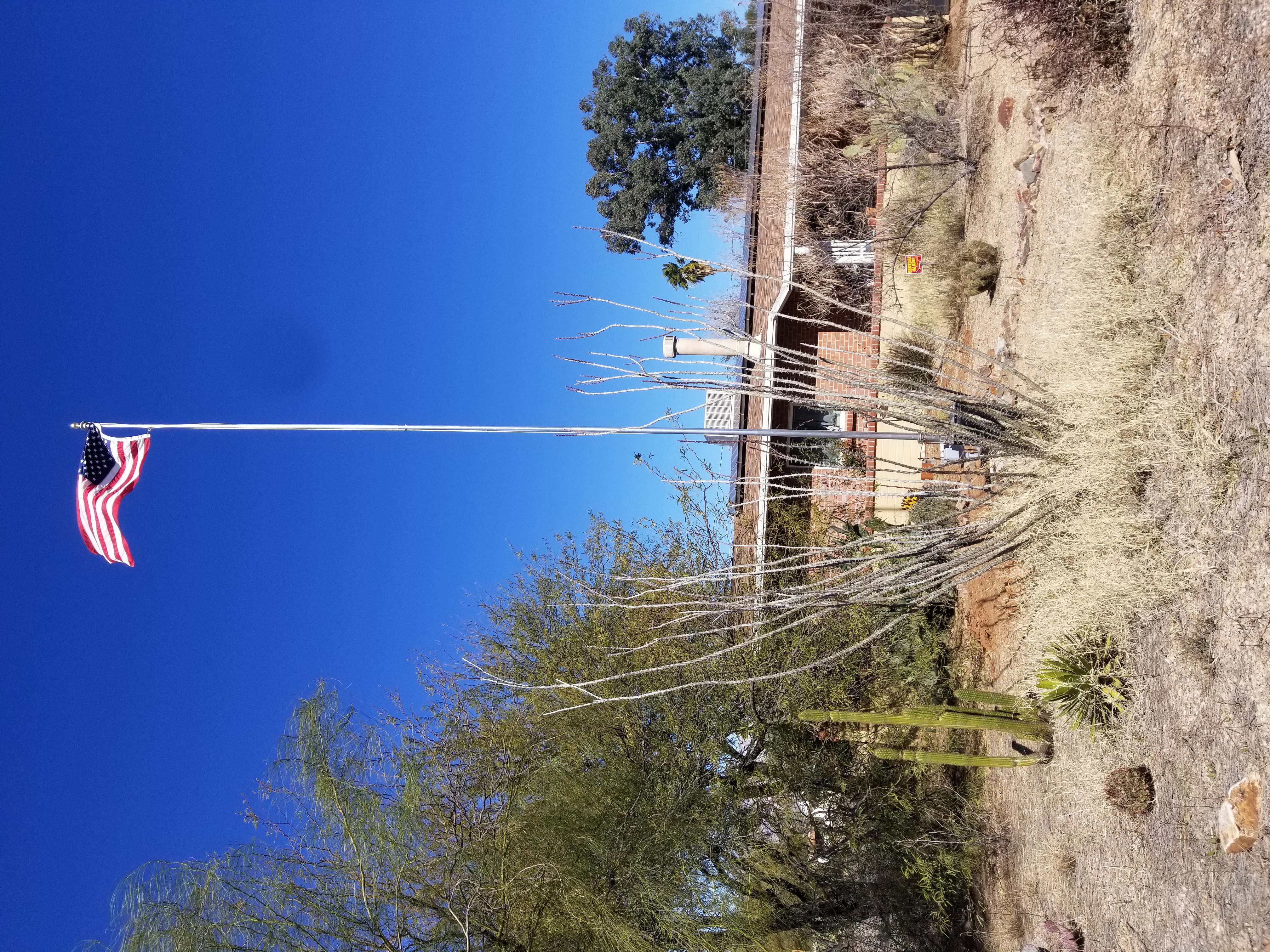
| The
Zero Five 30 Foot Flagpole Antenna as seem from the street. The MFJ 998RT antenna tuner is the black box at the bottom.
|
 |
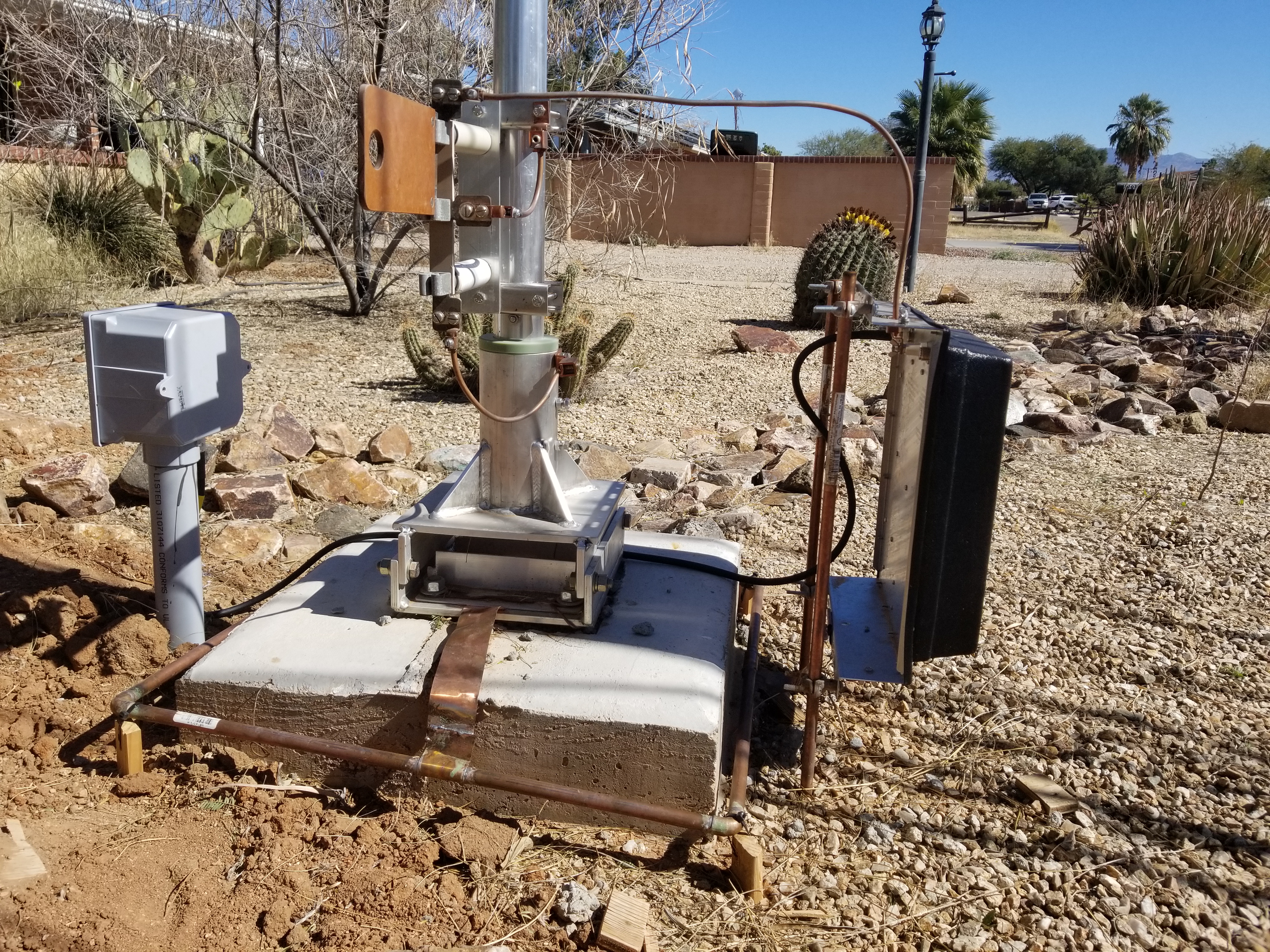
The image at the right shows the base of the antenna as currently installed. The concrete
base is two feet in diameter (with a two foot by two foot square top) that extends 40 inches below the surface and six
inches above. There are five #5 vertical rebars, each 36 inches long. They are tied to three 18 inch diameter "stirrups" made with
#3 rebar.
There is an Ufer ground consisting of 20 feet of 8 AWG
bare copper wire in the concrete with the excess coiled at the bottom of the hole. The ground wire is connected to the
tilt base of the antenna by wrapping it around one of the J bolts and held down with the associated flat washer and nut.
In addition, 2 inch wide copper strap is routed through the tilt base and held down with two pieces of angle aluminum,
each held in place by the mounting J bolts. The copper strap connects to the radial "ring" construced out of 1/2 inch
copper pipe.
On the right, the MFJ 998RT antenna tuner is mounted on two eight foot ground rods. Copper strap also goes
from the antenna tuner to the radial ring.
On the left is a plastic junction box on top of two inch plastic conduit buried 2 feet. The conduit carries the RG-8/U transmission line.
The end of the coax in the junction box has a PL-259 connector that connects to an SO-239 bulkhead mount barrel connector in the bottom of the box.
A short piece of RG-8/U goes from that SO-239 to the input of the MFJ 998RT antenna tuner.
There is a 3 position J plug mounted on insulators on the antenna mast. The bottom connection is connected to ground through
the antenna base using 1/4 inch copper tubing. The middle connection is connected to the mast using 1/4 inch copper tubing.
The top connection is connected to the antenna tuner output using 1/4 inch copper tubing. For normal operation, the J plug
is between the middle and top connection, connecting the antenna tuner to the mast. During storms, the J plug is moved to
the bottom connection grounding the antenna. In addition, an ammeter J plug was modified by removing the ammeter and installing
an SO-239 connector. This can be placed between the bottom two connections to make antenna impedance measurements.
Finally, the base is surrounded by 1/2 inch copper pipe to serve as a "radial ring." The photo was taken before the radials were added.
There are 16 radials as described here.
|
 |
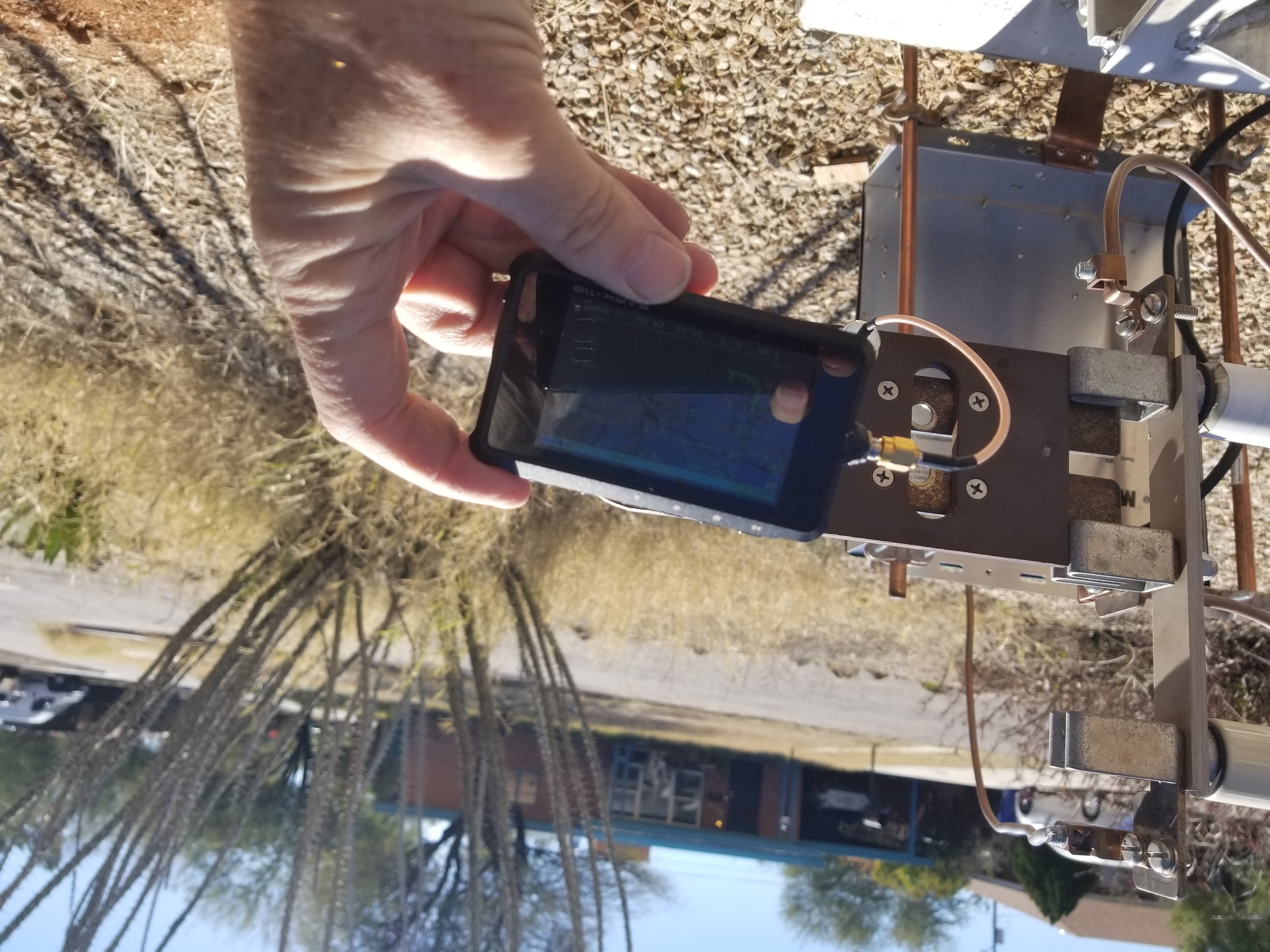
| The image at the right shows a base impedance sweep being made. A J-plug designed for inserting an ammeter was modified to add an SO-239
instead of the ammeter. The SARK-110 antenna analyzer is plugged into the SO-239. As discussed above,
the three terminal J-plug socket has the top terminal going to the MFJ 998RT antenna tuner, the middle to the
antenna mast, and the bottom to ground. The antenna analyzer is measuring the impedance between the bottom two terminals, or between the
mast and ground. |
 |
| The image at the right shows where the buried conduit comes up at the house. The RG-8/U from the coduit passes through a hole in the wall to
another junction box in the house. In addition, a short piece of RG-58/U passes through the hole. The RG-58/U has a PL-259 on the end in the outside
junction box. The PL-259 is connected to a bulkhead mount SO-239 barrel. On the outside of the box, another piece of RG-8/U goes to the
vertical VHF/UFH antenna. Finally, a short piece of 6 AWG bare copper wire passes through the hole in the wall and connects to an 8 foot ground rods
near the junction box. |
.jpg) |
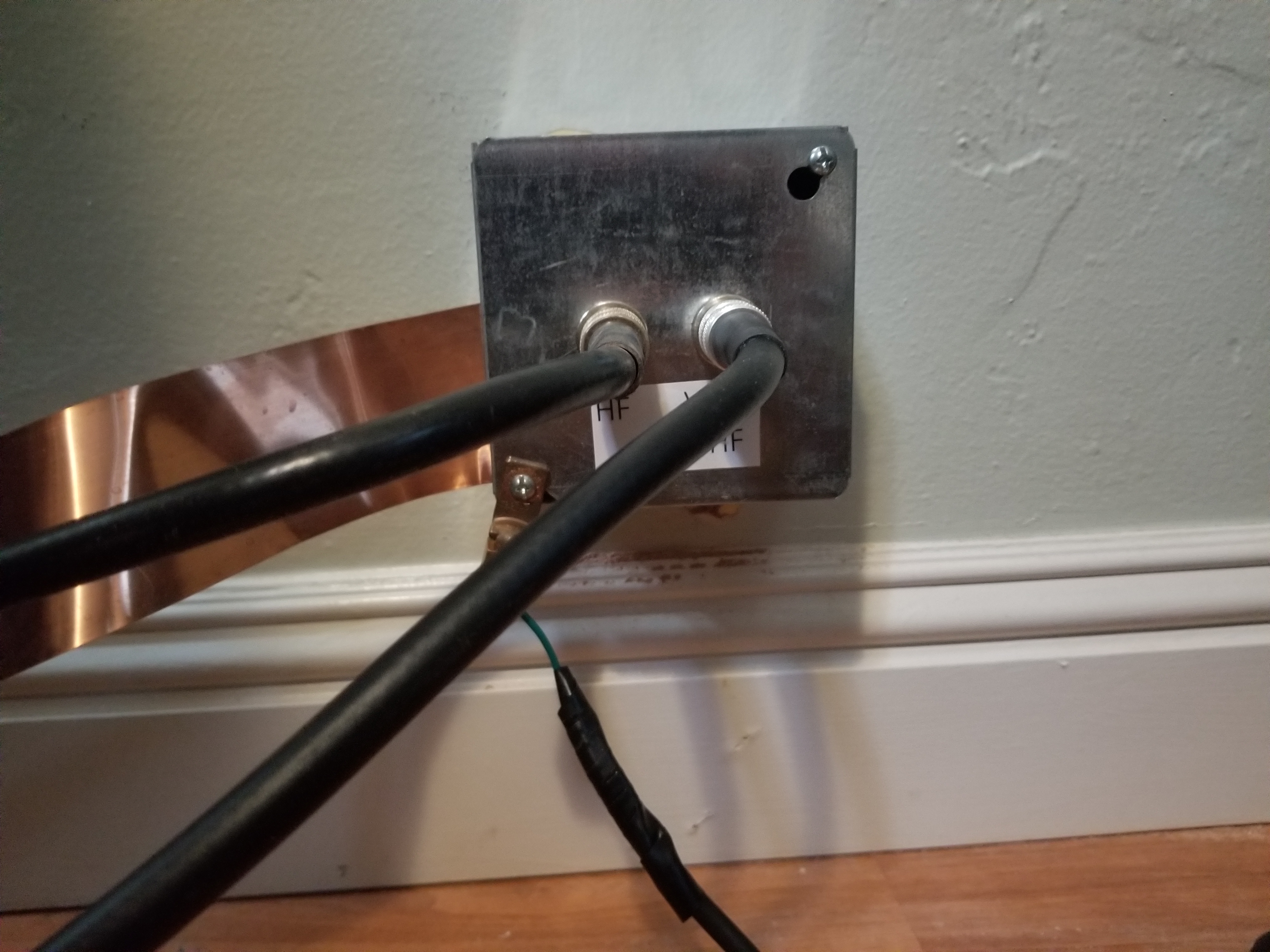
| The image at right shows the junction box inside the house. The RG-8/U from the buried conduit is connected to the left SO-239. The RG-58/U os cpmmected tp
the right SO-239. The 6 AWG wire connects to the ground screw in the junction box. The left cable goes to the directional wattmeter after the
Dentron Clipperton L amplifier. The right cable goes to the Wouxun VHF/UFH transceiver.
Two inch copper strap is clamped between the box cover and the box and provides an RF ground to the
SEA245 transceiver and the Dentron Clipperton L amplifier. The wide copper strap has lower RF resistance
and reactance than wire with the same crossectional area. The short 6 AWG ground wire between the inside junction box and the ground rod should contribute
minimal impedance. Similarly, the very short piece of RG-58/U should contribute a minimal amount of loss to VHF/UHF. |
 . . |
Antenna Model
Richard Fry provided this analysis on the antenna.
Below is some number-crunching for those systems, starting with the use of NEC4.2. In addition, I used EZNEC PRO 7.0 to model the antenna
in the middle of each of the HF amateur bands. Those results are here.
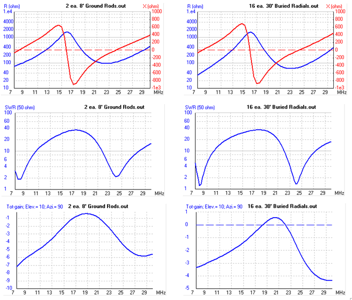
Ground Rods vs Ground Rods with Buried Radials with 5 mS/m Ground Conductivity
- ASSUMPTIONS
- Operating Frequency = 7.2 MHz
- Earth Conductivity, Permittivity = 5 mS/m, dc 13 (average soil)
- Conductors = Copper-clad
Ground Rods When Used = Two each; Vertical Plane Separation = 1 meter
CALCULATED VALUES
- Radiation Resistance, 30' Monopole = 27.5 ohms
- Monopole Feedpoint Terminal Z, Base Driven
- with Ground Rods = 76.9 -j50.2 ohms
- with 16 Equally-spaced, Buried Radials; each 30' long = 35.2 -j51.3 ohms
- ESR of System Path to RF Ground Potential (Conductors + Soil Loss)
- with Ground Rods = 49.4 ohms
- with Buried Radials = 7.7 ohms
- Antenna System Gain (max @ 26 deg elevation)
- with Ground Rods = -4.4 dBi
- with Buried Radials = -0.7 dBi
- System Radiation Efficiency* EXCLUDING the ESR of the Matching Network in Use
- with Ground Rods = 27.5/(27.5 + 49.4) x 100% = 35.7 %
- with Buried Radials = 27.5/(27.5 + 7.7) x 100% = 78.6 %
*Using the "classical" method, NOT the same as shown for these systems using the
methodology of NEC-based software.
/Richard Fry, October 2022
Ground Rods with 15 mS/m Ground Conductivity
The feedpoint impedance with ground rods (76.9 -j50.2) is quite a bit different than the measured impedance, below, at 7.2 MHz (39 +j11). The assumptions in the above model
include that the ground conductivity is 5 mS/m. According to the FCC M3 map, the ground conductivity of Tucson AZ is 15 mS/m. Richard ran the
model again with the higher ground conductivity.
In addition to ground conductivity, the models use the ground dielectric constant. Typical dielectric constants are shown below.

.png)
Increasing the ground conductivity from 5 to 15 mS/m decreased the driving point impedance from 76.9 -j50.2 ohms to 68.7 -j38.1 ohms, but the resistance is still considerably above
the measured 39 ohms, and the reactance substantially different (predicted -38.1 ohms, measured 11 ohms). A possible explanation for the difference is the coaxial feed line from
the antenna tuner to the transceiver acting like a single ground radial. The line extends about 30.75 feet from the antenna tuner, then has excess coiled, forming a common mode choke.
The line is on gravel about 3 inches thick, making this a slightly elevated radial.
To test whether the coax is acting as a ground radial, the cable was disconnected from the tuner and another impedance sweep run. As shown below,
the connection or disconnection of the coax has a minimal effect.
Ground Rods with Ufer Ground with 15 mS/m Ground Conductivity
It's interesting that the measured driving point impedance is lower than what is
shown by the model. It seems like the most likely reason is that the ground resistance
is less than predicted. Above is the consideration that the feedline is acting as
a radial. As shown above, disconnecting the coax had a minimal effect on the driving
point impedance. The antenna also has an
Ufer ground. It is
20 feet of 8 AWG wire passing through the 46 inch concrete base with the excess
coiled at the bottom. Richard Fry added the Ufer ground to the model and compared
it with the antenna with only the ground rods.
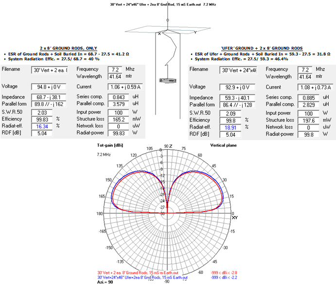
The driving point impedance dropped from 68.7 -j38.1 ohms to 59.3 -j40.1 ohms.
Subtracting out the radiation resistance of 27.5 ohms, the ground resistance
dropped from 41.2 ohms to 31.8 ohms. As noted below, the measured driving point
impedance at 7.2 MHz is 39.13 +j10. The gain increased from -2.8 dBi to -2.2 dBi.
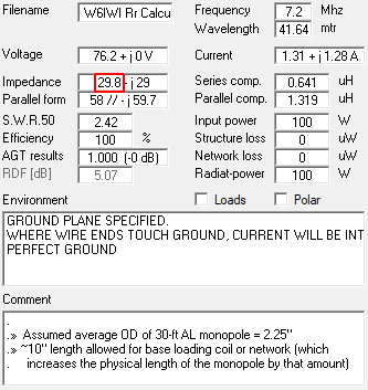
Consider Antenna Diameter
The vertical antenna is 2.5 inches in diameter at the base and 1.5 inches at the top. The model was modified to show the
average diameter of the radiator (2.25 inches). Previous models used a diameter of 20 mm (0.394 inches) To determine the radiation resistance, a perfect ground was used. The radiation resistance
increased from 27.5 ohms to 29.5 ohms. The measured driving point impedance at 7.2 MHz, listed below, was 39.13 +j10 ohms, leaving
about 10 ohms for ground resistance, which still seems low compared to the 31.8 ohms above that considered the ground rods and
Ufer ground.
Antenna Impedance Measurements
Antenna impedance measurements are being done as radials are added.
-
Two 8 foot ground rods (mounting tuner), no radials - Z at 7.248 MHz = 40.755 -j13.584 ohms. Note that the reactance goes to about zero at 7.609 MHz (Z = 52.393 + j0.515 ohms). The ARRL Antenna Book
section 9.2.3 puts the length of a quarter wave ground plane monopole antenna at 234/fMHz = 30.75 feet (pretty close to the 30 foot length). An ideal quarter wave monopole over perfect ground
has an impedance of 36.8 + j0 ohms. The difference of 15.4 ohms can be attributed to ground losses. The efficiency is 36.8/52.393 = 70%. The antenna should be resonant again at a half wavelength with a
high resistance and zero reactance. At 9.291 MHz, Z = 166.49 +j.028 ohms. It is interesting that this is not twice the 7.609 MHz where reactance was last zero.
- Since the MFJ 998RT needed to be removed for repair, I had the opportunity to compare the antenna
resistance with just the Ufer ground to the normal resistance with the Ufer and two ground rods. Impedance measurements are made
using a J-plug to connect the SARK 100 antenna analyzer between the antenna mast and the
antenna base. The base has a 20 foot copper wire going down into the concrete base with the excess coilded at the bottom (the Ufer
ground). The base connects to the radial ring (1/2 inch copper pipe) with 2 inch copper strap. The radial ring then has 2 inch copper
strap to the chassis of the antenna tuner which is mounted on the two ground rods. Removing the antenna tuner disconnects the ground
rods from the antenna base. The resulting antenna sweeps are
here. The resistance
variation seems minor with a more significant reactance change. For example, when adding the ground rods, Rs changes from 43.496 ohms
to 37.981 ohms at 7.128 MHz. X changes from -30.906 ohms to 18.107 ohms.
Relative Radiation Measurements
Signal to Noise measurements are being made at the Reverse Beacon Network station KO7SS, which is about 41 miles away. Ideally
this is close enough to reduce variation in signal strength due to skywave. The
graph shows there is still some variation (though some of these transmissions
were made at 500 watts instead of the usual 100 watts), it is hoped that with a large number of measurements, averages will show the
change in radiation from the antenna as radials are added.
Measurements are being
made about noon MST each day.
Effect of Radials
As discussed above the antenna originally had two ground rods and an Ufer ground. Over time, radial pairs are being added.
The results are described here.
Radial Repair 11/30/24
The yard work crew damaged several of the radials. The ones that were mangled were removed. Eight new radials were installed, every 45 degrees.
A plot of the impedance before and after the eight radials were added is here.
Elevated Radials
Some results with four elevated radials are here.
Additional Resources